- Home
-
Shop Now
- Fuser & Maintenance Kit
- PC / Logic Board
- Hard Drive/Mass Storage
- External Panel & Cover
- Paper Tray
- Paper Path Part
- Internal Part & Component
- Printer - Whole Unit
- Toner & Ink
- Network Interface
- Accessory
- Flatbed Scanner & ADF Assembly
- Image Transfer
- DesignJet/Plotter Part
- OfficeJet Pro
- Computer/Laptop Parts
- Technical Resources
- Contact Us
- Blog
- Laser Pros International | Laser Printer Parts
- >Blog
- >HP 59.F0 Error Tech Tip
Tech Tip - How to Resolve HP 59.F0 Error

Author: Ebben Joslin, Technical Support Supervisor
Published on December 17th, 2021
Covers:
– HP CP4025/CP4525/CM4540/M651/M680MFP Click Here to View PDF
– HP CP3525/CM3530/M551/M575 Click Here to View PDF
Description:
This error occurs when the printer boots up to the 59.F0 error and is unable to print. This behavior may be caused by one of the following conditions:
- A transfer alienation failure in which the ITB is stuck and unable to properly engage the internal transfer rollers.
- The SR9 sensor in HP CP4025/CP4525/CM4540/M651/M680MFP Models or the SR17 sensor in HP CP3525/CM3530/M551/M575 models (the primary transfer roller disengagement sensor), is dirty or has gone bad.
- The fuser drive assembly is damaged or broken. Typically, a grinding or clicking noise will be heard during boot up.
See the two sections below on how to resolve the 59.F0 Error.
Action for HP CP4025/CP4525/CM4540/M651/M680MFP Models
- Reseat the ITB and power cycle the printer.
- If the issue persists, completely remove the ITB from the unit and manually test the ITB gear and flag.
- Rotate the gear (callout 1) and check if the flag actuates (callout 2) when the white gear is turned.
- If the ITB flag is broken, damaged, or if the flag does not move, replace the ITB (CE249A)
- If the ITB gear and flag are working properly and is not damaged continue to step 3
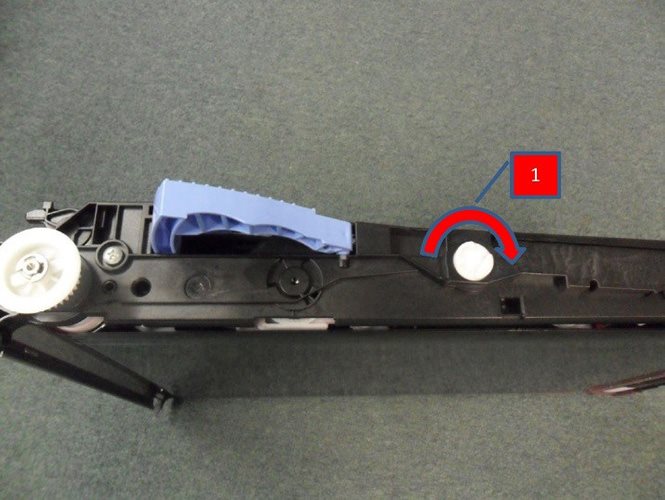
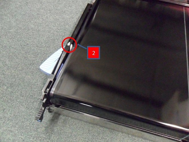
- Test the Primary transfer roller disengagement sensor SR9 (Sensor “K”) by using the MANUAL SENSOR TEST in the TROUBLESHOOTING MENU.
- NOTE: Before initiating this test, remove the ITB and fuser assembly from the unit to locate Sensor SR9 (callout 3) inside the fuser cavity.
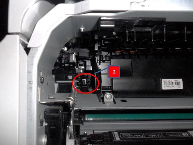
- From inside the fuser cavity, slowly press down and release the SR9 flag to actuate the sensor
- While pressing and releasing the flag, check the control panel display for sensor response (under K) and confirm the sensor toggles between 0 and 1 (The normal state is 0).
- If the value does not toggle between 0 and 1, possibly clean or replace the sensor (WG8-5696)
- NOTE: Before initiating this test, remove the ITB and fuser assembly from the unit to locate Sensor SR9 (callout 3) inside the fuser cavity.
- If Sensor SR9 is working properly, the error would then be the result of the fuser/transfer drive assembly not engaging the belt. Replace the fuser drive assembly.
- For duplex models RM1-5656.
- For simplex models RM1-6702.
NOTE: If the simplex drive is not available, the duplex drive unit can be used in its place, but not the other way around.
Action for HP CP3525/CM3530/M551/M575 Models
- Reseat the ITB and power cycle the printer.
- If issue persists, remove the ITB completely from the printer and inspect the ITB.
- Check to see if the ITB flag rotates (callout 1) when the white knob is turned (callout 2).
- If the ITB flag is broken, damaged or does not rotate, replace the ITB (CC468-67907).
- If the ITB flag is broken or damaged, continue to step 3
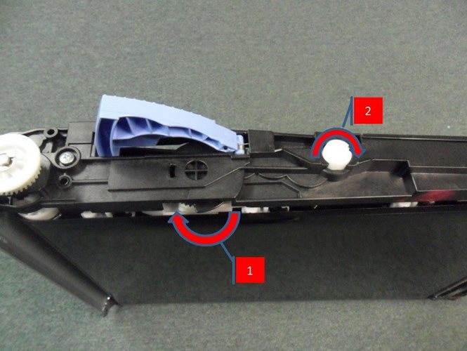
- If Sensor SR17 is working properly, open the right door and defeat the interlock switch. With the ITB removed, perform the ITB contact/Alienation test.
- From the printer control panel access Trouble Shooting/Diagnostics Menu
- Locate and select Component Test
- Press the down arrow to highlight ITB Contact/Alienation, then press OK.
- During the test (about 20 seconds), observe the white alienation drive hub located above the Cyan cartridge (shown with the arrow in the figure below).
- Locate SR17 through the right side of the printer.
- It is attached to the frame of the printer just about the end of the black cartridge (where it makes contact with the frame). Location of SR17 (circled) in image below.
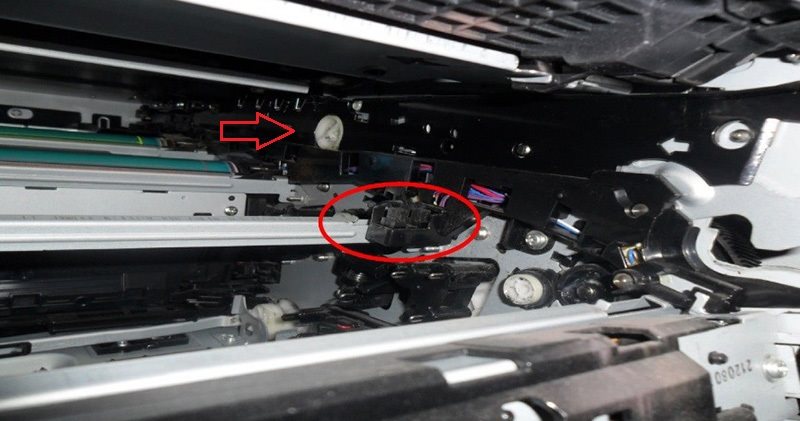
- Insert a piece of paper into the SR17 sensor bracket. The state of sensor “I” on the control panel should change to 1.
- Observe the control panel for proper operation of the sensor.
- If the value for sensor letter “I” does not change, the sensor will need to be cleaned or replaced (Photo interrupter SR17 WG8-5696).
- If the alienation drive hub does not rotate, the fuser drive is most likely the problem. Replace the fuser drive assembly.
- CP3525/CM3530:
- For duplex models: RM1-4974
- For simplex models: RM1-5001
- M551/M575:
- For duplex models: RM1-8134
- For simplex models: RM1-8169
NOTE: If the simplex drive is not available, the duplex drive unit can be used in its place, but not the other way around.
- CP3525/CM3530:
